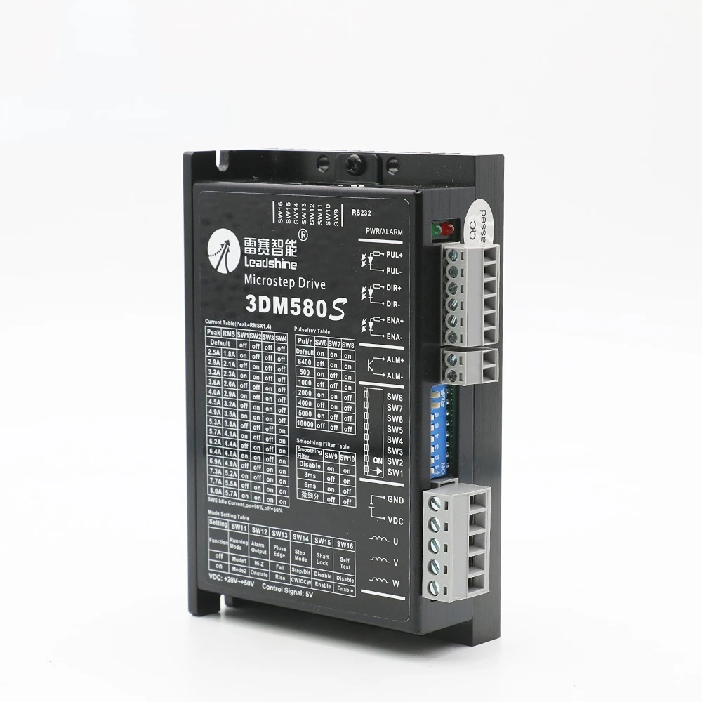
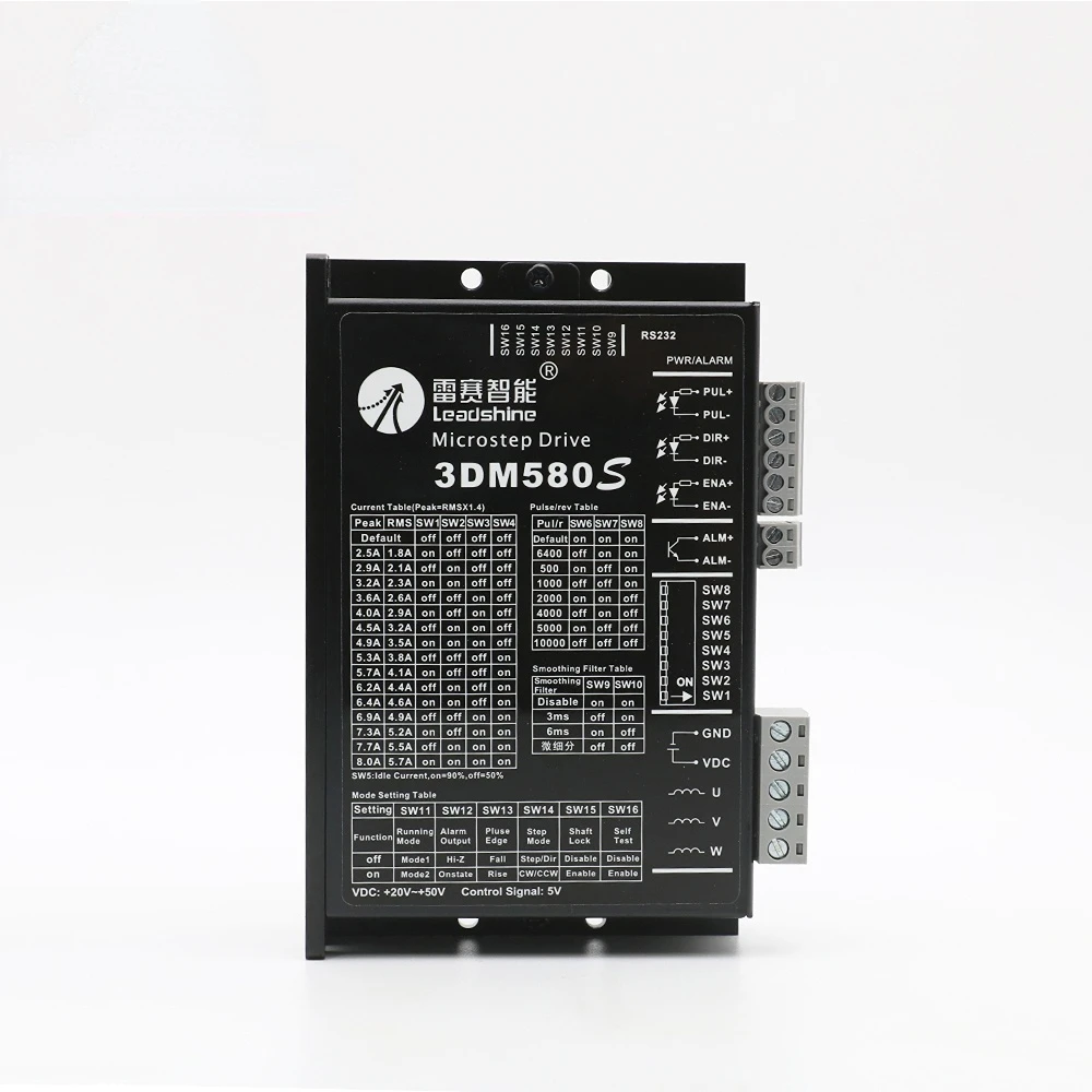
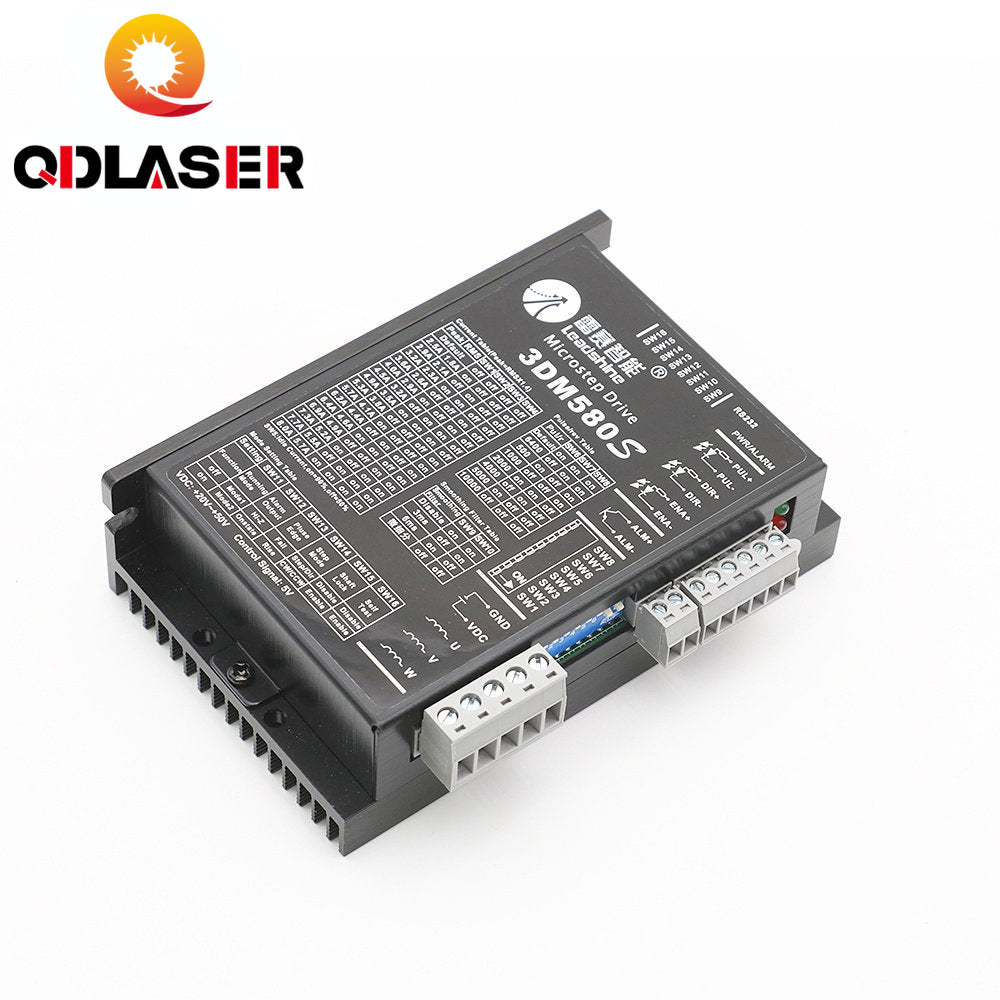
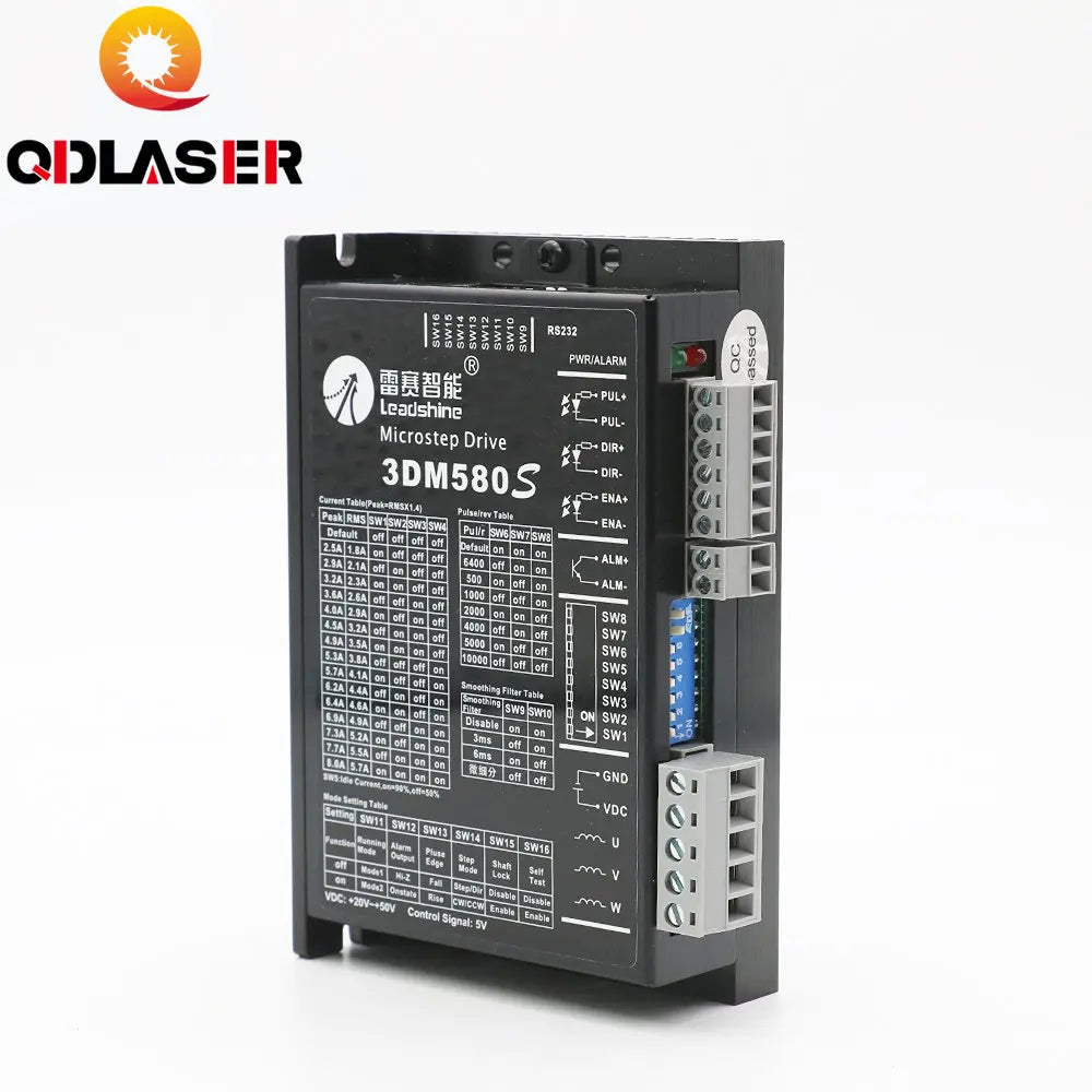
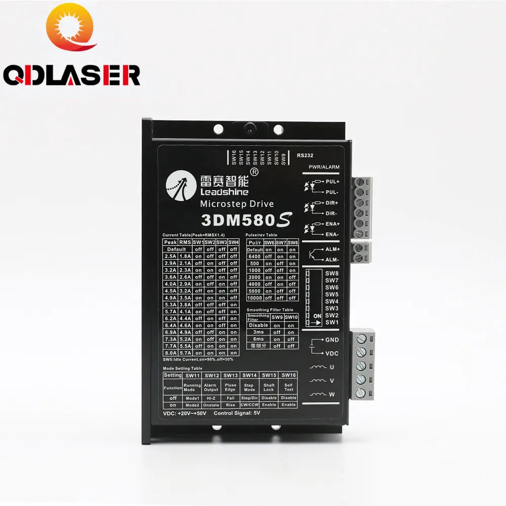
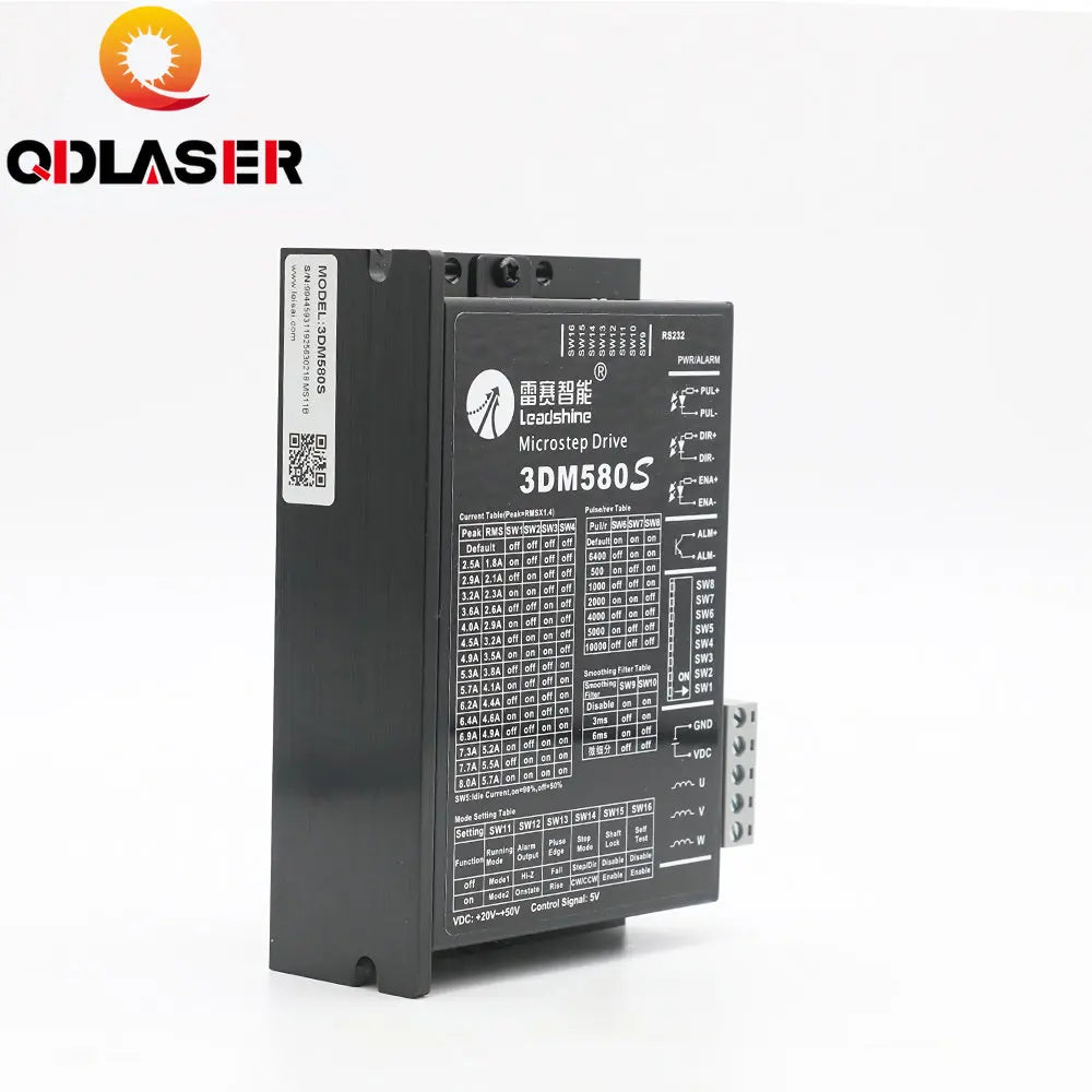
QDLASER Leadshine 3 Phase 3DM580s Stepper Motor Driver 18-50VDC 1.0-8.0A
QDLASER Leadshine 3 Phase 3DM580s Stepper Motor Driver 18-50VDC 1.0-8.0A
Couldn't load pickup availability
1. Anti-Resonance, provides optimum torque and nulls mid-range instability
2. Motor self-test and parameter auto-setup technology, offers optimum responses with different motors
3. Microstep resolutions programmable, from 200 to 51,200 steps/rev
4. Supply voltage up to +50 VDC
5. Output current programmable, from 1.0A to 8.0A
6. Pulse input frequency up to 500 KHz
7. TTL compatible and optically isolated input
8. Automatic idle-current reduction
9. Suitable for 3/6 leads Three-phase motors
10. Support PUL/DIR and CW/CCW modes
11. Over-voltage, over-current, short-circuit protections
|
P1 Function |
3DM580 Details |
|
PUL+ |
Pulse signal: In single pulse (pulse/direction) mode, this input represents pulse signal, each rising or falling edge active (software configurable);4-5V when PUL-HIGH, 0-0.5V when PUL-LOW. In double pulse mode (pulse/pulse) , this input represents clockwise (CW) pulse,active both at high level and low level (software configurable). For reliable response, pulse width should be longer than 2.5 us. Series connect resistors for current-limiting when +12V or +24V used. The same as DIR and ENA signals. |
|
PUL- |
|
|
DIR+ |
DIR signal: In single-pulse mode, this signal has low/high voltage levels, representing two directions of motor rotation; in double-pulse mode (software configurable), this signal is counter-clock (CCW) pulse,active both at high level and low level (software configurable). For reliable motion response, DIR signal should be ahead of PUL signal by 5 us at least. 4-5V when DIR-HIGH, 0-0.5V when DIR-LOW. Please note that rotation direction is also related to motor-driver wiring match. Exchanging the connection of two wires for a coil to the driver will reverse motion direction. |
|
DIR- |
|
|
ENA+ |
Enable signal: This signal is used for enabling/disabling the driver. High level (NPN control signal, PNP and Differential control signals are on the contrary, namely Low level for enabling.) for enabling the driver and low level for disabling the driver. Usually left UNCONNECTED (ENABLED). |
|
ENA- |
|
P2 Function |
3DM580 Details |
|
GND |
Power Ground |
|
+Vdc |
Power supply, 18~50 VDC, Including voltage fluctuation and EMF voltage. |
|
U |
Motor phase U |
|
V |
Motor phase V |
|
W |
Motor phase W |